A Guide to Optical Motion Capture
Richard Roesler
Contents*
Introduction
What is Optical Motion Capture
Traditional animation techniques often fail to accurately capture real human movement. Despite an artist's best intentions, human movement is simply to complex to draw by hand. Early in the 20th-Century, animators found they could take a film of a moving subject and copy it to a cartoon by physically tracing each frame of the movie, a process called Rotoscoping [1]. By the late 1980's and early 1990's, new methods of capturing a subject's motion digitally were being created. Optical Motion Capture (OMC), one such method for turning real-life movement into digital data, uses a number of cameras to film a subject from different views. These views are then used to reconstruct the movement in 3D, where it can then be applied to a computer model.
Today, OMC is used extensively in animation and special effects for major motion pictures. From animated family films, like 2009's 'A Christmas Carol', to live action blockbusters such as James Cameron's 'Avatar', OMC is used to capture the nuisances of an actor's performance and transfer them to an animated character. This brings a greater feeling of life and reality to characters that would be traditionally hand animated. Motion Capture can also provide a means for a director to better visualize CG scenes. Most of the vast landscapes in Avatar were completely computer generated. Using OMC, Cameron was able to hold a "virtual camera" in hands, and see how the scene changed as he physically moved the camera through it. This gives a director an immense amount of creative control when it comes to working with CG.
![]()
James Cameron on the virtual set of Avatar. With a "virtual camera" and OMC, directors can move through a CG scene as easily they could a real scene with a real camera.
Used without permission from http://www.frankrose.com/work2.htm
How Does Optical Motion Capture Work?
OMC uses a number of special cameras that view a scene from a variety of angles. Just like binocular vision allows humans to see the world in three dimensions, the use of two or more cameras observing the same subject allows us to rebuild that subject in 3D. In "Marker-based" OMC reflective markers are placed on the actor's body. Because of their reflectivity, these markers can easily be recognized by software in the camera. Recording the positions of these markers throughout the range of the motion, allows us to determine the position of the actor's body at any given time. Alternatively, "Marker-less" OMC tries to accomplish the same task without the use of special tracking devices. Instead, the actor's silhouette is viewed from different angles, and is used to reconstruct the entire 3D body of the actor. In the special effects industry, Marker-based capture is favored for is accuracy over the convenience of Marker-less tracking. In the remainder of this paper, we focus on Marker-based OMC.
Project Description
This project is an exploration into the inner workings of an Optical Motion Capture system. We focus mainly on the process of building the system and actually capturing the data, leaving the animation aspect of OMC to others. Roughly we split the entire process into three stages:
- Pre-Capture Setup - Preparing the stage and the subject for use
Capture & Data Acquisition - Tracking subject movement and building a 3D representation
- Post-Process Editing - Connecting the data to a simulated character skeleton
I have implemented a small one-dimensional sample of the marker detection and tracking algorithm that I will use as an example later on. The sample was written in Matlab and is available for download.
Pre-Capture Setup
Equipment
High quality motion capture requires an equally high quality setup. Special high-speed cameras are placed around the capture stage as to best see the actor's performance. The actor is outfitted with numerous markers so that any movement he or she may make will be captured by the cameras. The data from the performance is then sent to massive data stations which reconstruct the position of each marker in 3D.
Capture Stage
Although the stage where the motion capture takes place does not actually play an active role in the capture process, a number of special considerations still need to be made, in order to guarantee the best results. The first consideration one must make is exactly how large the capture area will be. If the area is too small the actor will not have enough room too maneuver, too large and the cameras will have trouble picking up the small markers. The size of the studio is then a function of how fine of detail needs to be capture, along with the quality and quantity of cameras available. When the area to be captured is very large, the space can be split up into multiple "zones of capture" [1]. Each zone has a number of dedicated cameras that only capture markers within that zone. This data can be stitched together to get the complete information for the entire movement.
The amount of light in the capture area also needs to be carefully controlled. Diffusing the ambient light in the room reduces the effect of stray reflections on the capture process. Any bright reflections in the room can be picked up by the cameras as new markers, greatly increasing the difficulty in detection and tracking. Uniform lighting across the whole stage is also needed, so that markers appear the same throughout the entire capture area. A solid color backdrop is often placed surrounding the capture area to mask any background objects and increase marker visibility.
Cameras
For high-end special effects, OMC uses cameras specially made for the task. These cameras must strike a balance between high resolution images and fast shutter speeds. The choice of camera, therefore, is driven by the movement that needs to be captured. Higher resolution cameras are able to better resolve smaller gestures and accommodate larger capture areas, at the expense of shutter speed. Alternatively, faster cameras are able to reduce the amount of blur caused by a fast moving subject, but at the expense of resolving power. Broader movements like walking or fighting, thus tend to require a faster camera, while more precise performances, such as smiling or frowning, require the accuracy of high resolution cameras.
Academy Award-Winning 'MoCap' specialist, Vicon, produces some of the best motion capture cameras in the industry. Their top-of-the-line Vicon T160 is capable of 16 Megapixel images at 120 frames per second [2]. When a faster shutter is needed, the resolution can be lowered to get speeds up to 2,000 frames per second.
Cameras are outfitted with special strobe lights that reflect off the markers for easy visibility. While these strobe lights could be visible spectrum lights, such as those used in studio photography, it has become common practice to use infrared lights instead. The amount of ambient interference in the infrared spectrum is significantly less than that in the visible spectrum. By filtering out all the ambient light a camera is able to easily distinguish between the reflective markers and the background.
Markers & Capture Suit
The type of markers we have been discussing this far are usually called "Passive Markers". Passive Markers are reflective and bounce light back at the cameras where they can be detected. As an alternative, "Active Markers" use LEDs that shine light toward the camera. Each active markers are able to flash at a unique frequency that makes marker tracking easier. However, this requires the actor to be suited in a set of wires to control each of the LEDs. Passive markers allow the actor more freedom and range of movement. Markers need to be place where the skin is closest to the bone and near joints in order to reproduce accurate movement. This usually means that actors must where a tight fitting spandex suit to which the markers are attached. For a full body motion, somewhere in the range of 50 markers is usually required [CITE GUERRA].
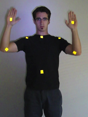
For my sample I used 8 pieces of retroreflective tape as upper body markers
Camera Calibration
The physics which govern the inner workings of a camera are frequently too difficult to model accurately. Instead, we mathematically represent a real camera as a theoretical "pin-hole" camera [4]. Light bounces off a subject and enters the camera at the camera center (theoretical analogue to the aperture) and is projected onto the image plane (CCD sensor). This is illustrated in image below. The large arrow on the right represents some object that we see in the world. As it passes into the camera it is projected onto the image plane.

`Diagram of a pin-hole camera. Notice that the image plane is shown in front of the camera center. This is for convenience, but doesn't affect the mathematical workings of the camera.
Let X be a homogenous 4-vector in camera coordinates of a position in the world:

We can find the point on the image plane that X would project to by:

where x is the 3-vector representation of the 2D image coordinates and P is a 3x4 projection matrix. As its names suggests, the projection matrix determines how a real-world point gets projected onto the image plane. Using similar triangles on our pin-hole camera, we are able to find that P is simply:
![\[
\left[ {\begin{array}{cc}
f,0,0,0 \\
0,f,0,0 \\
0,0,1,0 \\
\end{array} } \right]
\] \[
\left[ {\begin{array}{cc}
f,0,0,0 \\
0,f,0,0 \\
0,0,1,0 \\
\end{array} } \right]
\]](attachments/Optical_Motion_Capture_Guide/latex_7ac63e1fbb7a71f6b7c0d1194ec99a443526b7ae_p1.png)
Here f is the focal length of the camera. Of course, this simple representation ignores many of the complex ways light interacts with a lens and the sensor. In reality, the projection matrix for a camera if much more complicated. A real-word camera is defined by 11 intrinsic and extrinsic parameters. The intrinsic parameters tell how a world point is seen on the image plane and the external parameters tell how the the camera is oriented in the world. Let K be a 3x3 calibration matrix which holds the 5 internal camera parameters. Likewise, let [R|t] be a 3x4 transformation matrix which controls the rotation(R) and translation (t) defined by the 6 external parameters. Thus, we can redefine the projection matrix P as:
![$P=K[R|t]$ $P=K[R|t]$](attachments/Optical_Motion_Capture_Guide/latex_70e03f260ca356ed3a1dcbe74d268feb305536ce_p1.png)
P is still a 3x4 projection matrix, but we have now gone from a single degree of freedom (the focal length) to 11 degrees of freedom! The 11 degrees of freedom must be found experimentally through a process called camera calibration.
Classic Calibration [4]
We are able to find the projection matrix of a camera by solving the following equation for P:

This is the same equation as earlier, but we have written out x as its 3-vector homogenous representation. In order to solve this we are required to know the 3D coordinates of a point in space (X) and the corresponding images point (x). Rewriting this to solve for P we get:

where  is the i-th row of P. Since there are only two known equations and 12 unknowns this solution is underdetermined for a single point. In fact, we need at least six point correspondences to be able to find a solution. We get these 12 correspondences by using a "calibration object." This is basically a large checker-board of known size that we hold in front of the camera. If we know the real-word distances between corners of the checker-board we can determine their relative positions in the world. Knowing the relative world positions and the exact image positions of certain points on the board gives us enough point correspondences to perform the calculation.
Now let us return to our definition of P:
![$P=K[R|t]$ $P=K[R|t]$](attachments/Optical_Motion_Capture_Guide/latex_70e03f260ca356ed3a1dcbe74d268feb305536ce_p1.png)
If we allow the camera to be at the origin  and oriented such that its primary axis is parallel to the X-axis, then we can easily find K
  .
.
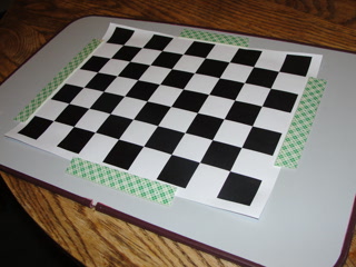
A checkerboard pattern being used to find the projection matrix of my digital camera.
Auto-Calibration [5
The classical method really works well for situations with one or two cameras, but is not well suited to motion capture. With cameras oriented at all positions around our capture stage the checker-board can only be seen by a few cameras at each time. In order to calibrate the cameras as a unit we must chain each of the calibrations together. Although a single calibration may be accurate, performing the calculation repeatedly is an error prone process. Instead, a new technique was developed allowing all of the cameras to calibrate automatically and at once. Instead of using a checkerboard pattern, the person calibrating the system waves a wand with two reflective markers a specified distance apart. These two points can be seen by every camera at once. If we know the distance between the two markers we know two points in the world coordinate system. Moving the want over a number of frames, we are able to accumulate enough points to calculate the projection matrix. Again, we assume R is the identity matrix and t is a zero vector, in order than our calculated P equals K.
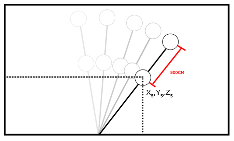
As the calibration wand moves through the scene, we can determine
the position of its markers according to relative distance between the markers
Camera Coordinate Frame to World Coordinate Frame
In both of the calibration schemes we have discussed thus far, we have found K by assuming some arbitrary coordinate system. To get the cameras in relation to the World Coordinate system one more step of calibration is required. A coordinate alignment frame is placed on the ground within the capture area. Typically this alignment frame is an L-Shaped object with markers at both ends and at the middle. As we already know the calibration matrix, we can determine the real-world X,Y values of each of the markers on the alignment frame. We also know the distance between markers on the alignment frame, which allows us to calculate the Z coordinate of each marker. The rotation and translation are then found as rotation and translation required to transfer the camera's coordinate system to that of the alignment marker.
Performance Capture
Once the pre-capture phase has been complete we can begin the actual work of capturing the actor's movements. This first requires us to automatically pick out all of the markers visible to each camera. Markers can appear at any position in the capture stage and at any angle toward the camera. Our marker detection algorithm needs to be robust enough to accurately find the markers. Once marker positions are known we have to be able to track the markers over time. Matching the markers in one frame to those in the next becomes more challenge as markers come in or go out of view. The maker positions calculated by each camera are then combined to get the 3D reconstruction of the 2D points.
Marker Detection
Marker detection begins by subtracting out the static part of the background. This removes most of the bright spots not associated with the actual capture area. Given a single image of just the background we can calculate the difference image as:

Digital Cameras tend to capture a fair amount of noise, so the RGB values of each background pixel may change slightly over the process of the capture. We can immediately improve our background subtraction by removing the average background pixels over the last n frames:

My implementation of the marker detection process begins with subtracting off the average pixel value of the first 100 frames of the video. The result can be seen below:
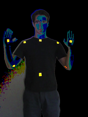
The difference image found by subtracting off the first 100 frames of background footage.
Of the pixels remaining, those that represent the markers should be the brightest. Applying a binary threshold to the image leaves us with a number of possible positions:

After background subtraction and foreground thresholding is applied
we are left with eight correct marker positions (green) and
one incorrect position (red).
Even after taking the foreground threshold there may still be some incorrectly identified markers. We can eliminate some of these by requiring that the diameter of the possible marker be between a certain range. In the image above this eliminates the incorrectly identified marker, leaving us with a correctly tagged image. The position of each marker is then said to be the centroid of the region defined by visible part of the marker.
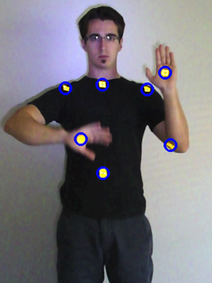
After background subtraction and foreground tresholding we
are easily able to locate potential markers
SEE FULL MOVIE: detectionMovie.mpg
My trials with marker detection where controlled enough that this simple algorithm worked consistently. A professional system would include a number additional methods for marker detection that would increase its robustness. [CITE Guerra] suggests a number of additional methods:
- Silhouette detection by calculating image gradient: Any potential marker must lie within the perimeter defined by the actor's silhouette.
- Corner detection: If square markers are being used, any corner detection algorithm should be able to locate them. Then, each marker position is defined as the average of the four corners that make up that square.
Marker Tracking
With more than 50 markers on an actor, tracking markers from one frame to the next can be a challenging task. As the actor moves throughout the scene some markers may become occluded (hidden from view) to many or all of the cameras. Increasing the number of cameras may help, but the overall problem cannot be avoided. For my demonstration, I used a thresholded nearest neighbor calculation to perform matching. Formally:
Marker A from frame i-1 is matched to marker A' in frame i, if distance(A,A')<distance(A,all other markers) and distance(A,A')< threshold
This algorithm only works in the simplest of circumstances. It did allow me, however, to identify a number of situations which make tracking difficult. One major problem is trying to assign markers when two or more markers overlap. This can be seen in the video included below. As my right hand passes over my right shoulder, the shoulder marker becomes occluded. The next closest visible marker is on my right hand, resulting in both the hand marker and the shoulder marker being assigned to my right hand. When the shoulder marker comes back into view, another problem becomes apparent. Namely, is the shoulder marker a new marker that we have never seen before or does it belong to a currently existing marker that is wrongly assigned. My program is unable to handle this situation, and the should marker goes unmatched.
![]()
Result of tracking with Nearest-Neighbor algorithm after 70 frames. See Full Video: trackingMovie.mpg
Clearly, well-designed motion capture studios have better means of dealing with correspondence ambiguities than we did. Doing point correspondence in 3D significantly helps the situation. If the motion capture cameras are well placed, any given marker should be visible to at least two cameras. By reconstructing the three-dimensional position of that point we can disambiguate it from other points. While the inner workings of professional motion capture software is proprietary, we would venture to guess that most make use of a filtering algorithm, such as the Extended Kalman Filter (EKF)[Cite Thrun].
3D Reconstruction
If we remember back to our description of a pin-hole camera we saw how a 3D point, X, projects onto a 2D pane as x. In motion capture, however, we only know the coordinates of the x and we need to determine the coordinates of the X If we project a ray starting at the camera center and passing through x, we see know that X must lie along that ray. However, with a single camera, we cannot tell how far along that ray X really is. If a second camera views that same point, we are again able to back-project a ray from the camera center through a point x' to X. Now we have two rays, whose equations we know, that pass through X. Finding the point X that satisfies this intersection constraint (called the epipolar constraint), gives us the three-dimensional coordinates of x and x'.
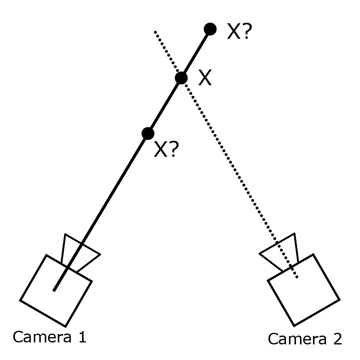
A ray back-projected from Camera 1 defines a line which X must lie on.
Back-projecting another ray, this time from Camera 2, defines the unique point X.[BR]
Post-Processing
Character Control
Even with proper marker placement and good tracking algorithms the data from the performance capture is not quite ready to use. We want to apply the 3D data to a virtual skeleton of the character we are trying to animate. As a marker moves in the data, we need it to move the corresponding skeletal bone along with it.
Spring Model Given enough markers we can find the position of each bone using a simple spring model. Imagine each marker as having a spring attached to it that pulls on the bone. The figure below demonstrates:
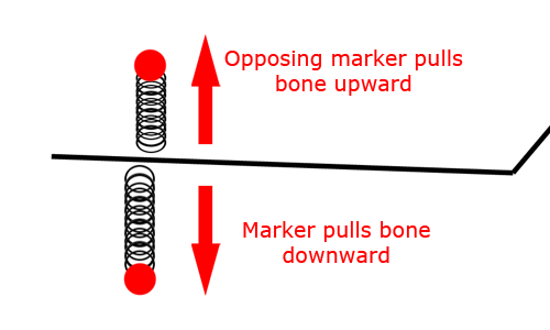
Spring Model for marker-bone interaction
Opposing springs keep bone in place
As a marker moves further away the spring connected to it elongates causing the bone to be pulled toward the marker. Markers on the opposing side of the bone, however, apply an opposing force that prevents the bone from moving too far. In this way, the random noise in our marker position measurements is canceled out by the damping of the spring system.
Inverse Kinematics When using a smaller number of markers we may not have enough information to use the spring model. Instead of rely on Inverse Kinematics. The movement of a human body is dictated by a number of mechanical rules. For example, if the actor lifts up his knee, both his upper and lower leg are moved correspondingly. In this fashion we can determine how all the joints in the actor move by in accordance with the position of the other joints. The equations required for Inverse kinematics are much more complex than those that govern the spring model, but they require fewer markers per joint. Typically, these techniques are combined by loosely coupling the bones to the markers. The Inverse Kinematic equations are still calculated, but the overall system system is less constrained because markers are not directly connected to the bones anymore.
Motion Editing
At this point the capture movements of our actor can be applied to a 3D character. One of the benefits of motion capture is that animators can manually tweak the movement data in order to get more desirable moves. For example, suppose we are doing facial motion capture for our movie's villain character. We want the character to have the traits of a real person, such as his diabolical smirk. However, after capture, the animators decide they want the smirk gesture to be even more evil looking. Motion editing allows animators to go in and modify how the actual movement data. This strikes the balance between an artists creativity and an actor's realism.
Sample Code
I implemented the marker detection and tracking sample in Matlab. It has a (moderately) easy to use GUI that goes along with it. The program works on a video split into frames and labeled by PREFIX00001.png I have really only tested it on the frame sequence used for this project, so I have included that in the folder as well.
Running the Program:
- Download and Un-Zip file onto your local computer
- Open Matlab and add the sample to your file path
run moCapGui(<file prefix>)
Download: http://stanford.edu/~rroesler/
References
[1] Trager, 'A Practical Approach to Motion Capture: Acclaim's optical motion capture system.' In "Character Motion Systems", SIGGRAPH 94: Course 9.
[2] Vicon. (2010). 'T-Series Product Brochure'. Available from http://www.vicon.com/products/
[3] Guerra-Filhol, G (2005). 'Optical Motion Capture: Theory and Implementation. In RITA. Volume XII. Num 2.
[4] Hartley, R. and Zisserman A. (2008). 'Multiple View Geometry in Computer Vision'. Cambridge University Press.
[5] Svoboda, T., Martinec, D., and Pajdla, T. (2005). 'A Convenient Multi-Camera Self-Calibration for Virtual Environments'. In PRESENCE: Teleoperators and Virtual Environments, 14(4).
